What is RoHS?
The member states of the European Union have issued a law, referred to as Restriction of Hazardous Substances (RoHS) Directive 2002/95/EU, restricting the use of certain hazardous substances in electrical and electronic equipment manufactured and/or sold within the EU. This Directive requires that all Electrical and Electronic Equipment (EEE) sold within the EU be free of lead, mercury, cadmium, hexavalent chromium, polybrominated biphenyls (PBB) and polybrominated diphenly ethers (PBDE), .
Impact of RoHS Compliance for Electrical Component Manufacturers
Of the six (6) substances included in RoHS Directive, lead is the one of primary concern for internal components and soldering of electrical converters.
In the electronics circuit assemblies, there are three sources of lead:
1. Solderable traces on the circuit board;
2. Solderable finish on the components themselves;
3. Solder used to connect the two in all variations: alloy, solder paste for reflow and liquid solder for wave.
Lead-free solder alternatives:
Conventional Sn60/Pb40 eutectic tin lead solder (liquid temperature: 183°C) can be successfully soldered at temperature of 220°C. By comparison, most (not all) lead-free solder alloys have a higher liquid temperature and require soldering profiles with peak temperature in range of 240-255 °C.
Lead-free component manufacturers’ alternatives:
1. To select the lead-free termination finish that is compatible to the lead free and the current tin lead
solders.
2. To modify the board so it can tolerate higher reflow or wave flow temperature associated with the
higher melting points of most of the lead-free solder pastes.
Most lead-free solder systems will require a peak reflow or reflow temperature from 240°C to 255°C.
Impact of RoHS on Surface Mount Soldering
The most common method used to surface mount components is reflow soldering, where a soldering paste is printed onto the paths of the circuit board, the components are set into place, with the pins placed into the paste and the board is then passed through a reflow oven. In this oven, the soldering paste is heated and melts to bond with the pins, securing the components to the board. In a single zone oven, all the pins are uniformly heated.
Potential Problem
· If the circuit board contains a mixture of components which require different soldering temperatures to bond to the board, will all components withstand the 255°C peak soldering temperature required to mount a lead-free electrical converter?
Options
· In low volume manufacturing situations, manual soldering may be an option.
· In other situations, the reflow soldering method, using liquid solder wave may be appropriate.
· Three (3) heat zone reflow ovens allow the soldering temperature to slowly increase to a designated temperature.
· The three heat zone ovens produce varying temperatures during the mounting process, but traditionally, all are within the range of the components mounted on the board.
· Seven (7) to nine (9) zone reflow ovens provide the most flexibility and versatility for temperature control. Each designated zone is assigned a temperature according to the threshold of component(s) in that zone. Circuit boards mounted through such ovens can have numerous components, requiring a variety of soldering temperatures, accurately mounted with minimum temperature variances to the board.
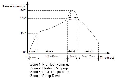
See Figure 1 SMD Soldering profile
Soldering Profile for RoHS Compliant through hole Converters
Lead-free technology mounting process:
Soldering methodology: Components can be mounted onto circuit boards manually with soldering iron or by the flow soldering method with liquid solder wave.
the most common methods of soldering are reflow and wave flow, where solder paste is printed onto the paths on the circuit board, the components are set into the place and then the board passes through a furnace. There the solder paste is heated and melting to bond the component on the board. All leads on the board are heated uniformly. The concern for lead-free soldering is when the temperature reaches the point of solder melting for some leads; it may have exceeded the heat threshold for other electronic components on the same board.
New method: The optimal conditions of surface or through-hole mounting are to ensure temperature uniformity on the board and lowering the peak temperature. To achieve these conditions, a furnace with seven to nine heating/cooling zones is required and the temperature profile must be carefully set. The temperature can be precisely controlled. Component placement is uniform with minimum temperature differences on the board.
Conventional method: Three heating zones. Heat rises more slowly where components are tightly packed, creating temperature differences on the board.
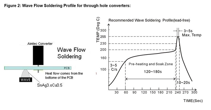
See Figure 2: Wave Flow Soldering Profile for through hole converters:
Notes: Information furnished is believed to be accurate and reliable. However, Aimtec assumes no responsibility for the consequences of use of such information nor for any infringement of patents or other rights of third parties which may result from its use. No license is granted by implication or otherwise under any patent or patent rights of Aimtec. Specifications mentioned in this publication are subject to change without notice. This publication supersedes and replaces all information previously supplied. Aimtec Products are not authorized for use as critical components in life support devices or systems without express written approval of Aimtec. © 2017 Aimtec – All Rights Reserved